
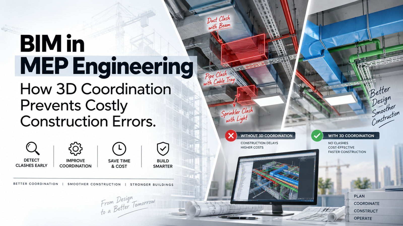
BIM in MEP Engineering: How 3D Coordination Prevents Costly Construction Errors
A building can look perfect on a drawing and still become a completely different story once construction begins. A duct passes through a beam. A pipe clashes with a cable tray. A fire sprinkler lands directly above a light fixture. An AHU access panel becomes impossible to reach after the ceiling is installed. These problems are rarely difficult to fix on a computer. Fixing them on site, however, can cost time, money and a lot of patience.
This is where BIM in MEP engineering becomes valuable. Building Information Modelling allows mechanical, electrical and plumbing systems to be developed in a coordinated three-dimensional environment before installation begins. Instead of relying entirely on separate 2D drawings, project teams can see how different building services occupy the same physical space and identify potential conflicts before they reach the construction site.
For developers, contractors and MEP consultants, BIM is no longer simply a visualization tool. When implemented properly, MEP BIM coordination becomes a practical method for reducing rework, improving installation planning, coordinating trades and making construction more predictable.
This guide explains how BIM coordination works, why MEP clashes happen, how clash detection prevents construction errors, and how developers and engineers can get greater value from a coordinated BIM workflow.
What Is BIM in MEP Engineering?
BIM, or Building Information Modelling, is a digital approach to planning, designing, constructing and managing buildings using information-rich 3D models.
In MEP engineering, BIM is used to create detailed digital representations of mechanical, electrical and plumbing systems. These systems can then be coordinated with the architectural and structural models to understand how everything fits together before physical installation.
An MEP BIM model may contain much more than the visual shape of an object. Depending on the project’s BIM requirements, elements can carry information such as equipment type, dimensions, system classification, specifications, manufacturer information and other parameters.
The real advantage comes when different disciplines are brought together into a federated BIM model.
A coordinated BIM environment can bring together:
- Architectural elements and room layouts.
- Structural beams, columns, slabs and walls.
- HVAC ducts and mechanical equipment.
- Domestic water and drainage piping.
- Fire protection piping and equipment.
- Electrical conduits, cable trays and busbars.
- Lighting fixtures and electrical equipment.
- Plumbing and sanitary systems.
- Plant rooms and equipment spaces.
- Access and maintenance clearances.
Why MEP Coordination Is Difficult
Modern buildings contain an enormous number of services packed into relatively limited spaces. Ceiling voids, shafts, corridors and plant rooms often become extremely congested.
Every discipline has its own requirements. HVAC needs sufficient space for ducts and insulation. Electrical systems require cable trays, conduits and access to equipment. Plumbing needs gradients for drainage and sufficient space for pipework. Fire protection systems have their own routing and coverage requirements.
At the same time, structural elements cannot simply be moved to accommodate services.
This creates a three-dimensional coordination problem.
A typical congested ceiling may contain:
- Supply and return air ducts.
- Fresh-air and exhaust ducts.
- Chilled-water and drain piping.
- Domestic water and drainage pipes.
- Fire sprinkler pipes.
- Electrical cable trays.
- Lighting fixtures.
- Fire alarm and ELV systems.
- Access panels.
- Structural beams and other architectural elements.
Looking at these services independently makes coordination difficult. Looking at them together in a 3D environment changes the entire process.
What Is MEP BIM Coordination?
MEP BIM coordination is the process of combining building service models and checking them against architectural and structural information to identify spatial conflicts, installation issues and coordination problems before construction.
The objective is not simply to make the model look clean. The model should represent an installation that can actually be built, operated and maintained.
MEP coordination typically involves:
- Collecting discipline-specific BIM models.
- Checking model quality and geometry.
- Federating architectural, structural and MEP models.
- Running automated or semi-automated clash detection.
- Reviewing clashes and determining their severity.
- Assigning coordination responsibilities.
- Developing practical routing solutions.
- Updating individual discipline models.
- Re-running coordination checks.
- Issuing coordinated drawings and models for construction.
What Is a BIM Clash?
A clash occurs when two or more elements occupy conflicting physical space or when their required clearances overlap.
The simplest example is a duct physically passing through a structural beam. But real-world coordination is more complicated than identifying direct intersections.
Common types of BIM clashes include:
- Hard clash: Two physical elements occupy the same space.
- Soft clash: Required clearance or maintenance space is not available.
- Workflow clash: An arrangement creates an installation or operational problem even though elements may not physically intersect.
For example, an electrical panel may technically fit inside a room, but if there is insufficient working clearance in front of it, the installation is still problematic. Similarly, an AHU may have enough space for installation but not enough room to remove a filter or access a service component.
Good BIM coordination therefore looks beyond simple geometry.
Why Clash Detection Matters in Construction
Traditional construction often discovers coordination issues sequentially. A contractor begins installing one service, another contractor arrives later and discovers that the required route is already occupied.
The result can be a familiar cycle:
- Stop the work.
- Raise an RFI or site query.
- Wait for a design decision.
- Redesign or reroute the service.
- Remove already-installed work.
- Reinstall the affected system.
- Inspect and approve the modification.
Every additional step can create cost and schedule pressure.
BIM changes the timing of this problem. Instead of discovering a conflict after installation, the project team can identify it while the systems still exist as digital geometry.
How 3D Coordination Prevents Costly Construction Errors
The biggest advantage of 3D MEP coordination is simple: problems are cheaper to solve before they are built.
1. Detecting Duct and Structural Clashes
Large HVAC ducts can create major coordination problems because they require substantial space. A duct route that looks perfectly acceptable in a 2D plan may intersect beams, columns or other services when viewed in three dimensions.
BIM allows the team to identify these conflicts before duct fabrication and installation.
2. Preventing Cable Tray Conflicts
Electrical cable trays frequently compete for space with HVAC ducts and plumbing services. Poor coordination can force cable trays to be installed at impractical elevations or require multiple site modifications.
In a coordinated BIM model, tray routes can be reviewed alongside other services and adjusted before installation.
3. Identifying Plumbing and Drainage Problems
Drainage systems are particularly sensitive to coordination because gravity drainage often requires a slope. A pipe cannot simply be moved up or down without considering its connection points and required gradient.
Early BIM coordination can identify situations where structural beams, ceilings or other services make the proposed drainage route impractical.
4. Avoiding Plant Room Congestion
Plant rooms are among the most coordination-intensive spaces in a building. Pumps, chillers, AHUs, electrical panels, tanks, valves, pipes and ducts all compete for space.
A 3D model makes it possible to review equipment arrangement, pipe routing, access zones and maintenance clearances before the plant room is constructed.
5. Protecting Ceiling Heights
Ceiling coordination is one of the most visible consequences of poor MEP planning. If services are not coordinated early, the required ceiling void can become deeper than expected.
This can affect architectural appearance, room heights and sometimes even the overall building design.
From 2D Drawings to 3D Coordination
2D drawings remain an important part of construction documentation, but they represent a three-dimensional building through separate plans, sections and details.
This means the coordination process depends heavily on the ability of engineers and contractors to mentally visualize how systems interact in space.
A 3D BIM model reduces this dependence on mental visualization by showing the physical relationship between systems directly.
With traditional 2D coordination, teams may have to:
- Compare multiple drawings manually.
- Check different floor plans and sections.
- Identify elevations from separate documents.
- Interpret service routes from symbols and lines.
- Coordinate revisions between multiple drawings.
With coordinated 3D BIM:
- Services can be viewed together.
- Conflicts can be detected spatially.
- Sections can be generated from the model.
- Equipment clearances can be reviewed visually.
- Coordination decisions can be communicated more easily.
The MEP BIM Coordination Workflow
A successful BIM coordination process needs more than software. It requires a defined workflow, clear responsibilities and regular coordination cycles.
Step 1: Collect Project Information
The BIM team begins by collecting the latest architectural, structural and MEP design information.
- Architectural BIM model.
- Structural BIM model.
- HVAC drawings and equipment schedules.
- Electrical drawings and load schedules.
- Plumbing drawings.
- Fire protection drawings.
- Equipment specifications.
- Ceiling and interior layouts.
Model coordination becomes unreliable when outdated drawings or models are used. Establishing the correct project information at the beginning is therefore essential.
Step 2: Build or Update Discipline Models
Each discipline develops its own model based on the approved design.
The model should contain enough geometric information to support coordination. Modelling unnecessary detail can increase file size and coordination effort without improving the construction outcome.
Step 3: Federate the Models
Architectural, structural and MEP models are brought together into a common coordination environment.
This federated model provides the project team with a single spatial view of the building and its systems.
Step 4: Run Clash Detection
Clash detection software can compare different model elements and identify potential conflicts.
Typical clash tests may include:
- Duct versus structural elements.
- Pipe versus beam.
- Cable tray versus duct.
- Sprinkler pipe versus ceiling elements.
- Equipment versus walls.
- Equipment versus access zones.
- Pipework versus electrical systems.
Step 5: Review and Prioritize Clashes
Not every clash has the same importance. Some may require immediate design changes, while others may be acceptable within project tolerances.
Clashes can be categorized based on:
- Severity.
- Location.
- System importance.
- Construction sequence.
- Required clearance.
- Impact on other disciplines.
Step 6: Resolve the Clashes
Clash resolution should be treated as a coordinated engineering decision rather than simply moving whichever service happens to be easiest to move.
The team should consider system functionality, accessibility, gradients, structural limitations, code requirements, installation practices and future maintenance.
Step 7: Update the Models
Once coordination decisions are agreed, the relevant discipline models are updated.
This step is important because resolving a clash visually without updating the source model can create inconsistencies later.
Step 8: Repeat the Coordination Cycle
BIM coordination is normally an iterative process. New clashes can appear when one system is rerouted to resolve another conflict.
The objective is to progressively reduce significant coordination issues until the model reaches an acceptable level of coordination for the project’s next stage.
Clash Detection Is Not the Same as Clash Coordination
This distinction is important.
A software tool can identify that a pipe and cable tray occupy the same space. It cannot automatically determine the best engineering solution in every situation.
Clash detection finds the problem. Coordination solves the problem.
An experienced MEP coordination team evaluates the technical implications of each proposed change.
For example, moving a pipe may affect:
- Drainage slope.
- Ceiling height.
- Access to valves.
- Pipe support locations.
- Fire compartmentation.
- Other MEP services.
This is why BIM should support engineering decisions rather than replace them.
MEP Coordination in Ceiling Voids
Ceiling spaces are often where BIM coordination delivers immediate value. A typical ceiling may contain several layers of services with very little vertical space available.
A coordinated approach should consider not only whether services physically fit but also the order in which they will be installed.
Important ceiling coordination considerations include:
- Finished ceiling level.
- Structural slab level.
- Beam depths.
- Duct dimensions and insulation.
- Pipe sizes and insulation.
- Cable tray elevations.
- Sprinkler requirements.
- Lighting fixture locations.
- Access panels.
- Maintenance access.
- Installation and support requirements.
The goal is to create a coordinated service zone that can actually be installed without compromising the architectural design.
Plant Room BIM Coordination
Plant rooms deserve special attention because equipment density is high and maintenance access is critical.
A common mistake is to coordinate only the equipment footprint while ignoring the space needed to operate and maintain the equipment.
A good plant room model should consider:
- Equipment footprint.
- Pipe and duct connections.
- Valve access.
- Electrical panel access.
- Equipment removal routes.
- Maintenance clearances.
- Drainage requirements.
- Structural supports.
- Equipment replacement requirements.
- Safe personnel movement.
An equipment room that works geometrically but cannot be maintained efficiently is not a successful coordination outcome.
How BIM Reduces Rework
Rework is one of the most expensive consequences of poor coordination. When an MEP installation has already been completed, correcting a design conflict may involve dismantling finished work and disturbing other trades.
BIM helps move the problem-solving process earlier in the project lifecycle.
Without effective coordination:
- Clash is discovered during construction.
- Installation stops.
- Site team raises a query.
- Design team reviews the problem.
- Revised routing is developed.
- Installed work may need to be removed.
- Other trades may be affected.
- Schedule and cost can increase.
With effective BIM coordination:
- Potential conflict is identified digitally.
- Engineering teams review the issue.
- Alternative routing is tested virtually.
- Coordinated solution is approved.
- Construction drawings are updated.
- Installation proceeds with greater certainty.
Benefits of BIM for Developers
BIM is often discussed from the perspective of designers and contractors, but developers can gain significant value from coordinated building information.
1. Better Cost Predictability
Reducing rework and late-stage design changes can improve cost control. While BIM does not eliminate construction variations, it can reduce avoidable coordination-related changes.
2. Improved Construction Planning
A coordinated model provides the project team with a clearer understanding of how building systems occupy space and interact.
3. Fewer Site Conflicts
Resolving major MEP clashes before installation can reduce site disruption and trade conflicts.
4. Better Quality Control
Coordinated models and drawings give contractors a clearer installation reference and help reduce ambiguity.
5. Improved Facility Information
When BIM information is maintained through later project stages, the model can potentially support facility management, maintenance and future modifications.
Benefits of BIM for MEP Engineers
- Better spatial understanding of building services.
- Earlier identification of design conflicts.
- Improved coordination with architects and structural engineers.
- More reliable service routing.
- Improved communication with contractors.
- Better visualization of plant rooms and congested areas.
- More coordinated construction documentation.
- Greater confidence during design reviews.
Benefits of BIM for Contractors
Contractors can use coordinated BIM models to improve installation planning and understand the sequence of work before mobilizing resources.
- Reduced uncertainty during installation.
- Better understanding of congested areas.
- Improved trade coordination.
- Better prefabrication opportunities.
- Reduced field modifications.
- Improved material planning.
- Clearer communication with subcontractors.
- Potential reduction in rework.
BIM and MEP Prefabrication
One of the major opportunities created by accurate BIM coordination is prefabrication.
When service routes are coordinated and dimensions are reliable, certain MEP assemblies can be fabricated away from the construction site and brought to the building for installation.
Potential prefabricated MEP elements include:
- Pipe assemblies.
- HVAC duct sections.
- Plant room modules.
- MEP service modules.
- Bathroom pods.
- Electrical containment assemblies.
- Combined service racks.
Prefabrication can improve consistency and installation speed, but it depends heavily on accurate dimensions and reliable coordination. A fabrication model that is based on unresolved design information can simply move the problem from the construction site to the factory.
BIM and 4D Construction Planning
BIM can extend beyond geometry. When model elements are linked with project schedules, the model can support 4D BIM, where construction sequence and time are associated with building elements.
For MEP construction, this can help teams understand when different services need to be installed and how trades interact.
- Structural construction sequence.
- MEP rough-in activities.
- Equipment installation.
- Ceiling closure.
- Testing and commissioning.
- Final finishes.
This can make coordination more closely connected with actual construction planning rather than treating BIM as a standalone design exercise.
BIM and Quantity Take-Off
Because BIM models contain measurable building elements, they can also support quantity extraction and estimation workflows.
Depending on model quality and project requirements, information may be used to assist with quantities for:
- Ductwork.
- Pipework.
- Cable trays.
- Equipment.
- Valves and fittings.
- Electrical containment.
- Fixtures and accessories.
BIM-based quantities should still be reviewed against project specifications, drawings and procurement information. A model is not automatically a perfect quantity database simply because it is three-dimensional.
LOD and MEP BIM Coordination
Level of Development (LOD) is an important concept in BIM projects. It broadly communicates how developed and reliable a model element is at a particular project stage.
The required level of model development should match the intended use of the model.
A model used for early-stage design does not necessarily need the same level of detail as a model intended for fabrication or installation.
For MEP coordination, the model may need sufficient information to verify:
- Equipment dimensions.
- Connection locations.
- Service routing.
- Pipe and duct sizes.
- Insulation thickness.
- Access requirements.
- Maintenance zones.
- Support and installation considerations.
The right question is not simply, “What LOD is the model?” The more useful question is, “Is the model developed enough for the decision we need to make?”
Common BIM Coordination Mistakes
BIM technology can improve coordination, but poor implementation can create a false sense of security. A 3D model is only useful when the underlying information and coordination process are reliable.
1. Modelling Without Coordination
Creating detailed models for each discipline does not automatically produce a coordinated building. The models must be federated and reviewed together.
2. Using Outdated Models
Coordination based on old architectural or structural information can create additional problems instead of solving them.
3. Focusing Only on Hard Clashes
A model may have zero hard clashes while still having serious access, maintenance, installation or clearance problems.
4. Ignoring Insulation and Installation Space
Modelling only the nominal pipe or duct size can make a congested area appear less crowded than it will actually be after insulation, supports and fittings are installed.
5. Moving Systems Without Engineering Review
Moving a service to eliminate a clash can introduce another problem, such as incorrect drainage slope, excessive pressure loss or inadequate access.
6. Treating BIM as a One-Time Activity
Coordination should continue as the design develops. Major equipment changes, architectural revisions and structural modifications can create new clashes.
How to Set Up an Effective MEP BIM Coordination Process
A successful BIM workflow begins with clear expectations. Before modelling starts, the project team should establish how models will be created, exchanged, reviewed and approved.
Key project requirements should define:
- Model ownership and responsibilities.
- File formats and exchange procedures.
- Model naming conventions.
- Coordinate systems and project origin.
- Model development requirements.
- Clash detection rules.
- Coordination tolerances.
- Issue tracking procedures.
- Model exchange frequency.
- Approval and revision processes.
Clear BIM standards prevent coordination from becoming an informal process where every team follows a different approach.
The Role of the BIM Coordinator
The BIM coordinator acts as an important link between different disciplines. The role is not simply to run clash detection software and distribute screenshots.
A good BIM coordinator understands the spatial and technical requirements of the systems being coordinated.
The BIM coordination team may be responsible for:
- Managing federated models.
- Checking model alignment.
- Running clash tests.
- Prioritizing coordination issues.
- Managing clash reports.
- Organizing coordination meetings.
- Tracking issue resolution.
- Monitoring model revisions.
- Supporting coordinated drawing production.
The most effective coordinators understand both BIM workflows and actual construction practices.
From BIM Model to Construction Site
The real test of BIM coordination is not whether the model looks impressive during a presentation. It is whether the information helps people build the project correctly.
A coordinated model should ultimately support construction documents, shop drawings, installation layouts, fabrication information and site coordination.
Before issuing information for construction, the project team should confirm that major design and coordination issues have been addressed and that the model aligns with the latest approved project information.
BIM Coordination and Site Installation
During construction, coordinated BIM information can help supervisors and installation teams understand complicated service arrangements.
This is especially useful in areas such as:
- Ceiling service zones.
- Vertical shafts.
- Plant rooms.
- Electrical rooms.
- Utility areas.
- Service corridors.
- Basements and parking areas.
- Hospital service zones.
Clear 3D views and coordinated sections can often communicate complex installation requirements more effectively than a collection of independent drawings.
Why BIM Is Particularly Important for Complex Buildings
BIM coordination becomes increasingly valuable as building complexity increases.
Hospitals, airports, hotels, data centers, high-rise towers, laboratories and large commercial developments can contain highly congested MEP systems. These projects also tend to have strict requirements for reliability, access, redundancy and maintainability.
In such environments, resolving coordination issues after installation can be particularly disruptive.
A well-managed BIM process allows the design team to study complex areas before they become construction problems.
How Developers Can Get More Value From BIM
Developers should avoid treating BIM as a requirement that simply needs to appear in the consultant’s scope of work. The value comes from defining what the project actually needs BIM to achieve.
Useful BIM deliverables may include:
- Coordinated architectural and MEP models.
- Clash detection reports.
- Coordinated plant room layouts.
- Ceiling coordination views.
- Service shaft coordination.
- Construction coordination drawings.
- Fabrication-ready information where required.
- As-built BIM information.
- Asset information for facility management.
The BIM requirements should be linked to actual project outcomes instead of focusing only on model appearance or file delivery.
What a Good MEP BIM Model Should Achieve
A successful MEP BIM model should ultimately answer a practical question: Can the systems represented in this model be built, operated and maintained as shown?
A coordinated model should provide confidence that:
- Major services have practical routes.
- Systems fit within available spaces.
- Structural elements are respected.
- Required access is maintained.
- Equipment can be installed and serviced.
- Ceiling heights are protected.
- Service shafts are adequately sized.
- Major coordination conflicts are resolved.
- Construction information reflects the coordinated design.
Frequently Asked Questions About BIM in MEP Engineering
What is BIM in MEP engineering?
BIM in MEP engineering is the use of digital 3D building models to design, coordinate and manage mechanical, electrical and plumbing systems. MEP models can be combined with architectural and structural models to identify spatial conflicts before construction.
What is MEP BIM coordination?
MEP BIM coordination is the process of reviewing mechanical, electrical and plumbing systems together in a 3D environment to identify and resolve clashes, access issues, routing problems and other constructability concerns.
How does BIM prevent construction errors?
BIM allows potential conflicts between building systems to be identified digitally before physical installation. Engineers and contractors can test alternative solutions and coordinate the final arrangement before materials are installed on site.
What is clash detection in BIM?
Clash detection is the process of identifying conflicts between elements in different BIM models. Examples include ducts intersecting beams, pipes crossing cable trays, equipment conflicting with walls or insufficient maintenance clearance around equipment.
Is BIM better than 2D drawings?
BIM and 2D drawings serve different purposes and are often used together. BIM provides a three-dimensional coordination environment, while 2D drawings remain important for construction documentation and specific installation information.
Can BIM reduce construction costs?
BIM can help reduce avoidable costs associated with coordination errors, rework, site modifications and inefficient installation. The actual savings depend on project complexity, BIM implementation quality and how effectively the coordinated information is used during construction.
When should MEP BIM coordination start?
BIM coordination should begin early enough to influence design decisions rather than waiting until construction is about to start. Early coordination is particularly valuable for plant rooms, shafts, ceiling zones and other areas where space is limited.
Is BIM only useful for large projects?
Larger and more complex projects generally have greater coordination requirements, but BIM can also provide value on smaller developments where multiple MEP systems must share limited space. The level of BIM effort should be proportionate to project complexity and requirements.
Does BIM replace MEP engineers?
No. BIM is a tool used by engineers and project teams. Software can identify geometric conflicts, but engineering professionals still need to determine whether a proposed solution is technically sound, code-compliant, installable and maintainable.
Final Thoughts
Construction errors are often expensive not because the solution is technically complicated, but because the problem is discovered too late.
A duct that clashes with a beam may take minutes to reroute in a digital model. On site, the same issue can involve multiple contractors, dismantling, material wastage, revised drawings, delays and additional labour.
This is the real value of BIM in MEP engineering. It shifts coordination from the construction site into a controlled digital environment where problems can be identified, discussed and resolved before they become physical problems.
But BIM should not be reduced to attractive 3D models or automated clash reports. Effective BIM coordination combines accurate modelling, engineering knowledge, construction experience and disciplined communication between project teams.
For developers, that means better predictability and fewer avoidable surprises. For engineers, it means greater control over complex service coordination. For contractors, it means clearer installation information and fewer site conflicts.
Ultimately, the goal is straightforward: design it correctly, coordinate it digitally, and build it right the first time.